Brake lines and corrosion seem to go hand-in-hand. Corroded brake lines will leak, which should be immediately apparent by a complete loss of hydraulic braking power, which is exactly what happened to me (luckily in a parking lot). Replacing these lines can be problematic, mostly because they can be in difficult-to-reach locations, and the fittings are also most likely frozen by corrosion.
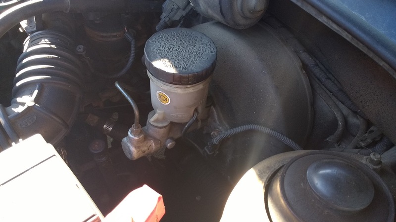
Here is how the brakes work: The brake pedal pushes a piston through the firewall. This motion is assisted by engine vacuum by the brake booster (which looks like a large cylindrical object on the firewall). The hydraulic pump (or master cylinder) is mounted directly on the brake booster, and also contains a reservoir for the brake fluid.
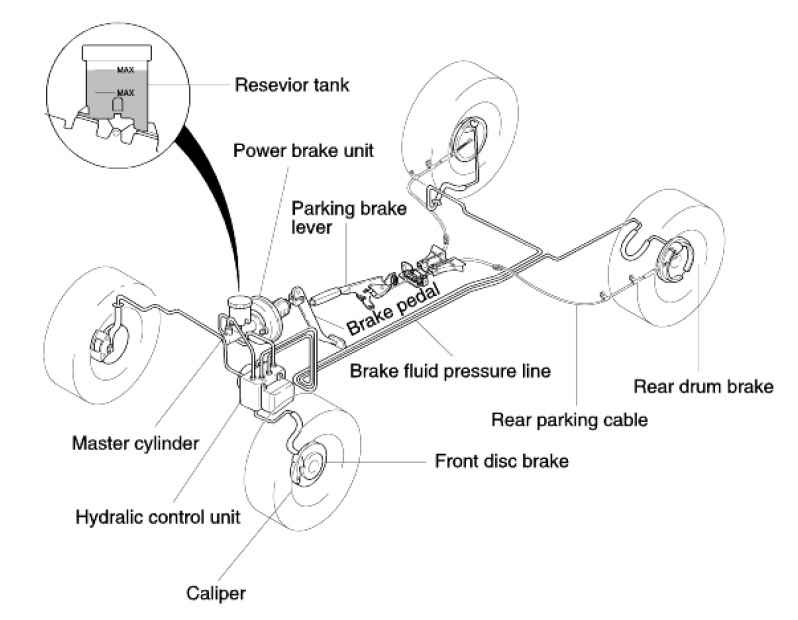
Two lines from the master cylinder connect to the hydraulic control unit. This is also mounted on the firewall, and is responsible for distributing the hydraulic pressure to each wheel. Four lines come out of the control unit and each one goes to a wheel. Under normal braking conditions, all four wheels will receive equal pressure. Under heavy braking, the front wheels receive a higher pressure. The lines to the two front wheels are fairly short and are sheltered by the engine compartment, so they are not likely to corrode. The rear lines run the entire length of the vehicle underneath, and are exposed to road salt and water. This is where most of the corrosion can be found.
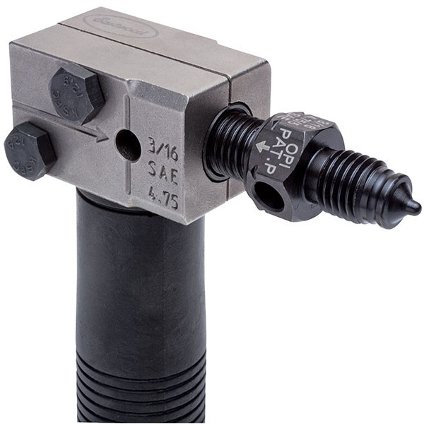
Replacing brakes lines is not a difficult task by itself, but replacing the full length of a brake line can be cumbersome because they involve a lot of bends and turns. Therefore, most people only replace the corroded sections by splicing in a new line. Brake lines are made of rigid stainless steel, and can be easily cut with a rotating pipe cutter. A new connection requires a union. Before connecting a union, the lines have to be fitted with male fitting and the ends of the tubes have to be flared. The shape of the flare is important because it forms a perfect metal-to-metal seal with the female end of the union. Most importantly, the flare prevents the tube from separating from the fitting under high hydraulic pressures. Double-inverted flare is the most common flare shape, and it is the type used in the Kia Rio (this information is hard to find online, but it is specified in the Kia Technical manual). The fitting threads are M10 x 1 (metric). The best and most economical tool I have found for creating tube flares is the Eastwood on-car flaring tool for 3/16 brake lines. It is easy to use and compact, and works on the Kia. Although pre-flared brake lines are cheap to buy, the exact length needed may not match up with standard lengths sold in stores. I had to cut off one end of the fitting and redo the flare for the correct length.

The problem was not solved even after splicing in the new lines. I was unable to bleed the brakes because all four bleed valves were completely frozen. These are small 8 mm screws, so they are very easy to round off.
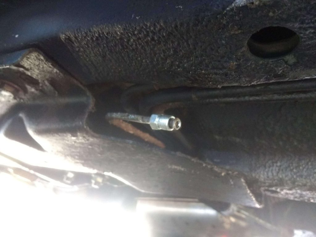
Attempting to remove one of them resulted in a broken screw, so it had to be drilled out. That ended up damaging the threads in the caliper, so the whole caliper had to be replaced. Also, both of the rear bleed valves were completely stuck and it was much easier to replace the entire brake cylinder rather than try to remove them. Even then, I ended up having to replace the brake lines leading to the cylinders because the connectors were complete frozen, and I had to cut the line to extricate the cylinder. While I was at it, it was also prudent to replace the rear brake drum, shoes, bearings and hub nut. All in all, a majority of the brake system was completely overhauled.


The hub nuts that hold the rear drum have to be replaced every time. These are not available at regular parts stores, and has to be ordered online. Instead of the cotter pin, these nuts are crushed to align with the slot in the axle (known as staking). This is best done with an air hammer and an axle nut punch tool.


The final step is bleeding the brakes to remove all air in the newly installed lines. Since the entire system was empty, first the master cylinder has to be filled and bled. This is done by removing the two outgoing lines from the cylinder, and using plastic tubes to run the line back into the reservoir. Then pump the pedals to purge out air from the cylinder.

Bleeding the wheels requires a vacuum suction to pull the fluid through the lines. This is best done with the Pneumatic Brake Fluid Bleeder with Auto-Refill Kit. Connect a compressed air line to create a vacuum (using the venturi effect), and the fluid can be pulled in through the bleed valve and collected into the tank. It is important to not let the fluid level drop in the master cylinder during this process to prevent air from being re-introduced into the lines. The kit comes with an inverted bottle which will automatically fill the master cylinder as the level drops.
Leave a Reply