Cylinder heads are very susceptible to heat. A single overheat incident due to a coolant leak or blower fan failure can cause the cylinder head to warp. That is exactly what happened in this case, so a rebuild was necessary. This is not a small job. It took 2 months to do this, but admittedly most of that time was spent waiting for parts or tools to arrive. After completing this work, the vehicle was running like it was new, absolutely quiet and smooth. It was a satisfying end, and I learned a lot of things about engines during the process.

Tear Down
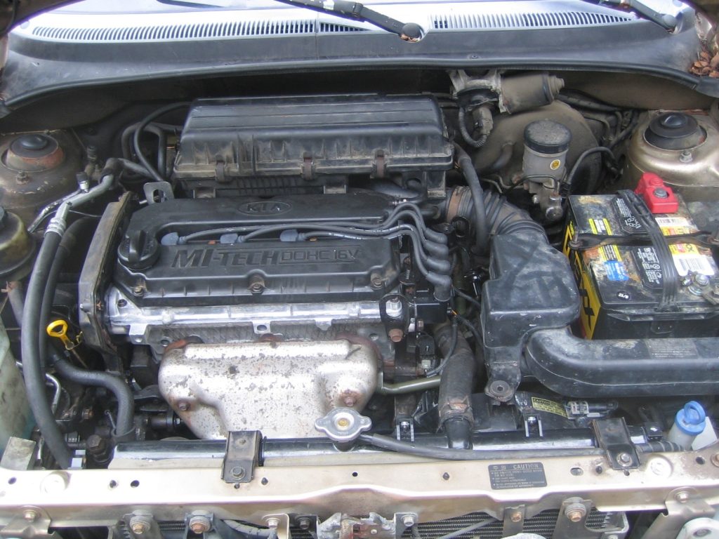
This is not a complete how-to list, but only the note-worthy items are listed.
- Although not absolutely necessary, removing the radiator, windshield washer reservoir and battery will create a lot of extra room and will make the work significantly easier.
- Use Ziploc bags to organize the nuts and bolts and to prevent losing them.
- Take lots of photos before things were dismantled and wires were removed, so that they can be reconnected without too much trouble.
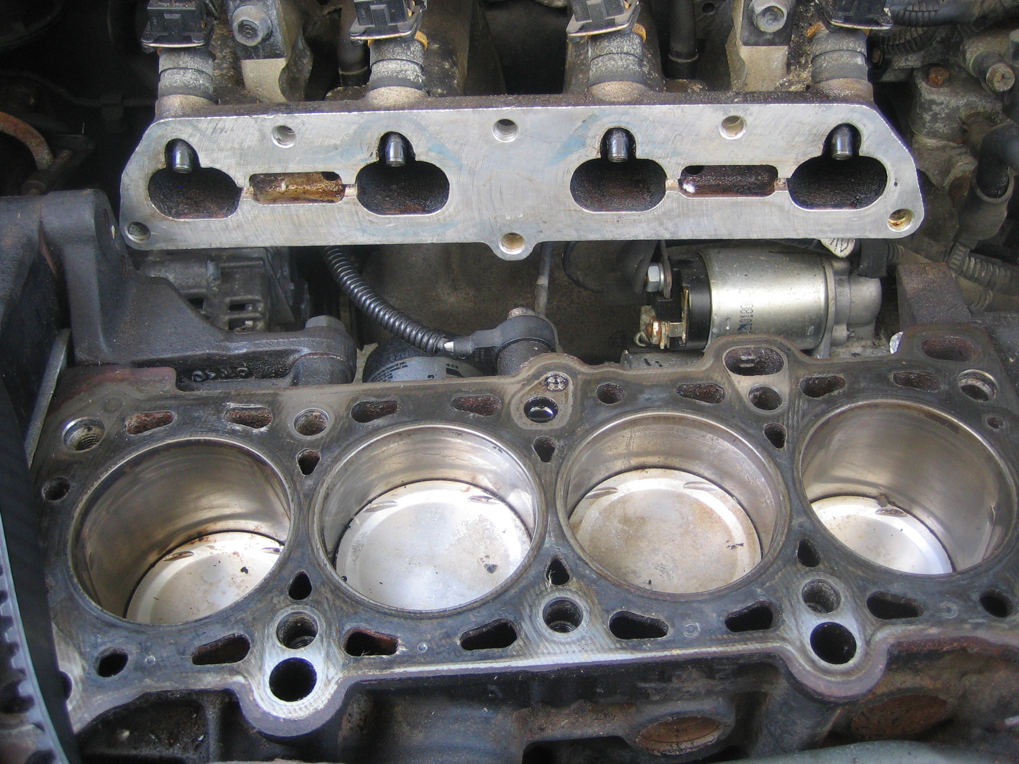
- The intake manifold is not easy to remove. In addition to the manifold bolt, the assembly is also held by two extra bolts on a lower horizontal support plate bolted to the frame under the engine. These bolts are not visible from the top, and it will not be immediately apparently what is preventing the manifold from moving.

- Removing the water pump pulley is very tough due to the tight space. There is not much space even for a strap wrench. The easiest method by far is to loosen the bolts while the drive belt is still on and under tension (duh, isn’t this is the ideal strap wrench?). During installation, just hand tighten the pulley bolts, then install and tension the belts, and then finally tighten the pulley bolts.
- Get a few Sunex long-arm ratcheting combination wrench. Despite its high price, it will make reaching bolts in difficult areas much easier.
- Power steering pump and alternator are mounted with a bolt in a sliding slot to allow adjustment of the belt tension. But grime build up may prevent the mounting bolt to slide easily in the slot. It may be easier to remove the entire mounting plate.
- The head bolts will require 12mm 12-point deep sockets. These sockets can be bought individually at Lowes instead of buying a whole set from auto parts stores. The removal pattern is important, but if the cylinder head is warped anyway, it doesn’t really matter. Once all the bolts are off, it should be easy to simply lift the head off the block. It probably weighs about 30 pounds.


The warp was 0.010” on the cylinder head and 0.002” on the deck. The deck was within spec, but the head was significantly warped. An automotive machine shop can fix this easily. The cost was $120 for machining, cleaning and pressure testing. It came back totally clean and dry.

A strong solvent is necessary to clean the deck. “Aircraft Remover” works well. A blade is useful for scraping the old gasket off the surfaces. Do the same for the intake manifold. The pistons can also be sprayed with the same stuff and wiped off.
Rebuild Kit
The parts needed for rebuilding the cylinder head are:
- Head gasket set – in addition to the main head gasket, a rebuild kit will also include all the other gaskets, such as for the intake and exhaust manifolds, water pump, thermostat etc.. New valve guide seals will also be included.
- Head bolt set – these bolts should not be reused because they get stretched during installation.
- Water pump – the water pump in the Kia Rio is in a tough place, and there is no better time to replace it than during a head rebuild.

Valves
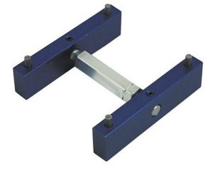
- This is a good time to also replace the valve seals, even if they had passed the leak test. Removal of the valves requires a valve compression tool. The generic C-clamp tools won’t work because the Kia valves are recessed inside a hole with very little space around it.
- The Lisle valve keeper tool is a better choice. It works for removal as well as installation, but it does require a lot of force to get the keepers to snap back in place. This youtube video made it look really simple, but I had to struggle a great deal. Some recommended using a hammer, but after trying it, I didn’t like the idea of using a hammer to compress a spring (not to mention it didn’t work most of the time). I ended up using a a wooden bar across the handle to give it extra leverage to push down on it. That made the process quite a bit easier.
- Removal of the valve stem seals also require a special tool. Pulling it with pliers did not work, and even with the special tool it took a lot of wrestling to get the seals off.
- The exhaust valves had a lot of white buildup. They were impossible to clean with a brass wire brush. So all of the valves were sent to a the machine shop for cleaning and refacing. Cost was just $2 per valve, and they came back the same day. They used a heavy duty steel wire-brush to clean the valves, and a precision grinder to polish the sealing face along the edges. Most of the advice on the internet seems to recommend against steel and to use brass. But these valves are made of hardened steel, so it is unlikely to get damaged from a steel brush.


- The exhaust valves had a lot of white buildup. They were impossible to clean with a brass wire brush. So all of the valves were sent to a the machine shop for cleaning and refacing. Cost was just $2 per valve, and they came back the same day. They used a heavy duty steel wire-brush to clean the valves, and a precision grinder to polish the sealing face along the edges. Most of the advice on the internet seems to recommend against steel and to use brass. But these valves are made of hardened steel, so it is unlikely to get damaged from a steel brush.


- The valve stems should be fully lubricated with oil before inserting them into the holes. The next step was to lap the valve seats. This requires a valve lapping tool and lapping compound. When reading about it, this process sounds a bit mysterious, but it is really simple. The lapping sound changes from a low-pitch grinding noise to a high-pitched squeaky sound, which is when the valve should be lifted and the process repeated a few times. Then thoroughly wipe the area of all traces of the lapping compound. The idea behind lapping is to make the contact areas smooth but lightly grooved concentrically so that they can seal well.


Hydraulic Lash Adjusters
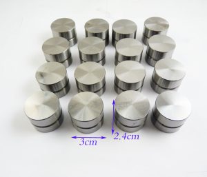
- The HLA (Hydraulic Lash Adjuster) are the silvery cylindrical buckets that slide through the holes and push on the valve stems. These are most easily inserted and removed with a magnetic pickup tool. I had assumed these were just cylindrical blocks of metal and hadn’t given them much thought, until I installed the camshafts and discovered to my dismay that all the valves remained open by random amounts with no relationship to the cam lobes. After some reading, I found out that the HLAs are not just pieces of cylindrical blocks, but are miniature oil reservoirs. They are designed to smoothly ride on the camshaft lobes to keep the valves continuously in contact with the camshaft. If there is even a small gap, it would result in a hammering action that could cause the camshaft to erode, and also make the engine noisier. The HLAs contain a spring-loaded piston and a check valve to hold pressurized oil inside. During installation they should contain air instead of oil. This makes them compressible when pushed by hand. When the cam starts turning, the air in the pistons will be driven out and oil will be sucked in. As it fills with oil, the check valve locks in the oil. Since oil is a lot less compressible than air, the HLAs become stiff. This makes the piston push against the valve stem instead of compressing. It is a very clever design because the HLA automatically adjusts its thickness to compensate for the play between the cam lobes and the valve stems. Without these HLAs, we would need precisely machined spacers, and the pieces may have to be re-machined periodically to adjust for changes in the cam lobes. The only problem with these HLA’s is that whenever the camshaft is removed, the pistons inside the HLAs will automatically inflate and will fill with oil from the surrounding area. Once they expand, they cannot be put back in service without draining the oil out first. Doing so might cause the valves to malfunction. The Kia is an interference engine (meaning the pistons can contact the valves if the valves are open when the piston is at the top dead center) so this is an important consideration.
All of my HLAs were full of oil and were solid as a rock. HLA’s are definitely reusable, and it can be pretty expensive to replace all 16 of them. The pistons can be pulled out with a long-nose locking vice grips. Regular pliers, even needle nose pliers didn’t work.
- I mounted the HLA on a bench vice (with towels) and locked the vice grip and pulled while turning. It slips a number of times, but eventually the piston pops out. It’s a matter of patience and technique. Once it pops, oil pours out that looks like black tar. This is oil that has been locked in there for ten years or more. Once you know the technique, it will take less than five minutes to disassemble all sixteen HLA’s.

- The internal parts of the HLA’s piston assembly can be pried apart easily. It contains the piston itself, a check valve and a small spring. The check valve can also be disassembled quite easily by prying out the frame that holds a steel ball inside a hole. I cleaned these pieces in Brakeleen, oiled them and reinserted them back into the HLA body. The parts should be lubricated with oil, but the piston cavity should not be filled with too much oil – otherwise it won’t compress. The HLAs initially need to be compressible in order for them to inflate to their proper heights.


Camshaft
- One camshaft is a bit longer and has an extra piece at the tail for triggering the camshaft position sensor. It is also best to check that this tail piece is securely screwed in before putting the camshaft in. The front oil seals should also be replaced, and should be included in the head gasket seal kit.

- Before installing the cam carrier, sealant (Ultra Grey) has to be applied in a bead, avoiding the oil pathways. The tightening torque calls for 10 ft-lb, which is pretty low for a torque wrench, so it may be ok to just use a hand wrench.

Water Pump
- This is also a good time to replace the water pump because it is a cheap item. But the water pump turned out to be one of the most difficult tasks. It required the removal of both timing belt rollers, and four mounting bolts. These bolts are all hidden and hard to locate due to the tight space. It would have been impossible to identify these bolts without comparing against the new water pump.
- Before the water pump could be taken out of the vehicle, the water inlet pipe had to be disconnected. But its bolts were hidden behind the power steering pump. So that had to be removed. But it’s long mounting bolt could not be pulled out without interfering with the nearby brake lines. So the brake lines’ brackets also had to be removed at two locations to allow them to be moved a bit. Then the power steering pump was removed and moved out of the way without removing any of its hoses.
- Even with the power steering pump out of the way, the lower bolt on the water inlet connection was still blocked by a bunch of things – the oil dip tube, the power steering pump’s mounting bracket and the AC compressor. Removing the dip tube and the power steering pump’s mounting bracket would have given sufficient access, but the dip tube would not budge, and also one of the bolts on the steering pump bracket had been stripped by someone before. This is probably because the spacer used for the steering pump was blocking one of those bolts. Unlike most spacers, this one is inserted into the bolt hole, so it needs to be tapped out. The last mechanic who worked on this probably could not figure out how to get this spacer out so he must have tried to unscrew the bolt behind it without adequate access and ended up stripping it.
- After removing the old water pump, I replaced it with a new pump. The mating surfaces were cleaned. The manual says not to use any sealant, but a tiny bit of water pump sealant helps to hold the gasket during mounting, especially for this case since the water pump is in such a difficult position. I practiced using the old water pump how the insert it into position without dinging the mating surfaces. Then gasket sealant was applied on both sides of the paper gasket very thinly and glued it to the water pump. Mounting was fairly easy after that.

- Mounting the intake water pipe was also easier with the AC compressor and its mounting bracket out of the way.
- Now the AC compressor, power steering pump and the brake lines could be reinstalled.
Timing Belt
- It would be foolish to not replace the timing belt during this rebuild. This requires the removal of the crankshaft pulley, crankshaft bolt and the timing belt guide plate.
- Removing the crankshaft bolt was tough because the shaft is free to spin. Even an impact wrench did not work. It turned out that the simplest process was to remove the crankshaft position sensor (CKPS) and insert a screwdriver to jam the flywheel to lock the shaft while turning the bolt.


- In order to take the old belt out, the engine mount on the passenger side has to be removed. It was an easy step that took less than 15 minutes. I removed the bolt that holds the large rubber bushing and the two vertical mounting bolts while the engine was supported from the bottom near the oil pan drain plug with a hydraulic jack. Then the old belt out was taken out, and the new one put in.
Mounting the new cylinder head
- The first step was to move all the cylinders to the mid position. Then all the threaded holes for the head bolts were cleaned by spraying Brakeleen into the holes and blowing it with compressed air. Then a copper spray sealant was applied to both sides of the head gasket. This was a bit messy, and parts of the sealant peeled off when I flipped the gasket over to spray the other side. The gasket only goes one way on the engine deck. There is a tilted oil hole at the rear center of the engine deck which will only align with the gasket in one orientation.


- Placing the cylinder head was not difficult. It went in pretty easily into the alignment holes with only a small adjustment after it was placed. The head bolts were greased and lightly tightened. The sequence is specified in the service manyal. Two bolts are shorter than the others and they must go near the timing belt. The first step is to torque them to 36 ft-lb, loosen them all in the reverse order, and then re-torque them to 18 ft-lb. This 18 ft-lb seemed awfully low, until you make the required 90-degree turn afterwards, which raises the torque to about 50 ft-lb.

- The water pump inlet has a split fitting – one is the return from the radiator and the other is the return from the heater core with a small branch coming from the air intake box. The piece that carries the return from the heater core and air box is a long metal tube that runs under the exhaust manifold and around the engine. This fits into the split fitting with an o-ring seal, and is only held by a bracket almost a foot away from the fitting that goes onto one of the exhaust manifold screws. It is a very strange fitting. I realized that that the bracket had been accidentally bent when removing the exhaust manifold. It was easy to unbend it, but the exact shape of the bracket in relation to the fitting is probably important, so I bought a new one from the Kia dealer for $35.

- Before installing the timing belt, the pulleys need to be installed on the cams. The intake and the exhaust pulleys are exactly the same and have the same markings, so it is important to mount them correctly by examining the cam lobe locations and the firing sequence of the cylinders. The cylinder firing sequence is 1-3-4-2 where cylinder #1 is closest to the timing belt.
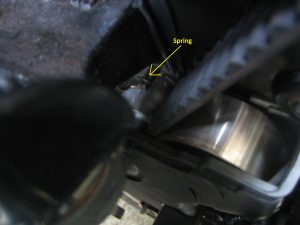
- Installing the timing belt was also more difficult than I had thought. The belt was extremely tight, and I could not get it on the sprockets. The only way was to remove the tensioning roller. That meant I also had to remove the water pump pulley and the crankshaft pulley. Having it done it once, it was easier the second time. Even then, I could not hold the camshafts in the right place due to the tension in the valve springs. So I bought the “Lisle dual overhead camshaft locking tool”, but it was too large and would not fit on this vehicle. After many tries, here is a trick that worked for me. After first lining up the crankshaft, I used a wrench to turn the exhaust camshaft to its correct position. While holding the wrench, I pulled the belt and slipped it on and used a cable tie to prevent the belt from slipping off the exhaust cam sprocket. Then I did the same with the intake pulley. To insert the tensioning roller, I used the wrench to turn the exhaust camshaft counterclockwise. This tightened the belt on the exhaust side and loosened it on intake side, which gave it enough slack to bolt the tensioning roller in place. Putting the tensioning spring back on was also tricky due to the confined space. I inserted a cable tie through one of the spring windings and pulled it from the opposite end to stretch the spring and slip it on to the post. The whole thing was surprisingly difficult for a simple timing belt installation.

- The valve cover had a lot of grime inside and out, and I had to soak and scrub with Brakeleen several times. The head gasket kit also came with a new valve cover gasket.
- After everything was re-assembled, and all the wiring plugged in, I squirted some oil into each cylinder through the spark plug holes and put some rag into each hole to prevent oil splash. I also put oil into the oil filter before screwing it on. After filling the engine with fresh oil, I removed the fuses for the fuel pump and the injectors and cranked the engine for a minute. The oil pressure warning light on the dash should extinguish by then. Then I filled it with coolant.
- Then I reinserted the fuses, installed new spark plugs and started the engine. To my pleasant surprise, it started right away without any hesitation. There was lots of smoke through the exhaust and through the front, but it seems to run fine. The smoke kept going for a long time, and I was concerned if something was wrong, but it went away after about an hour. The temperature was fine, and the radiator fan was cycling normally. It also sounded smoother than before.
- In the radiator cap, I could see small flakes of copper paint coming through, presumably from the head gasket. It was not too much to be concerned about.
Leave a Reply